From part to frame type
C-frames offer access for loading and tooling; four-column frames require assessment of guidance, table size and off-center loads; benchtop units require installation-space checks. Provide part and fixture drawings before selecting daylight, working stroke, support and load paths. Brochure family references are 10–2000 kN, 100–500 mm stroke (customizable) and 1–200 mm/s; these are not simultaneous ratings of one machine.
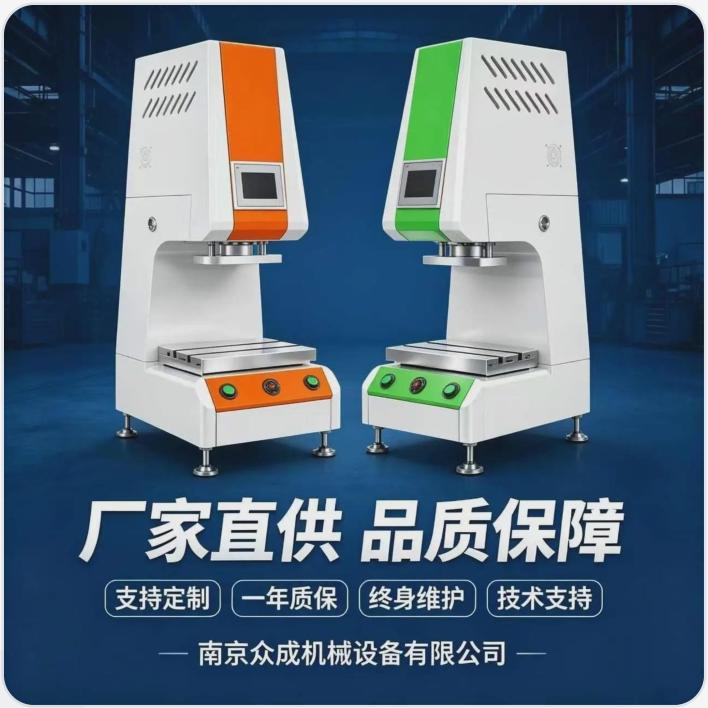 View full image ⤢
This Zhongcheng brochure image shows another C-frame benchtop arrangement. Use its appearance, panel and tooling layout for project discussion; final specifications, configuration and service terms follow the agreed contract.
Image source:Zhongcheng 2026 brochure · p.7 · original imageCylinder force and speed are linked
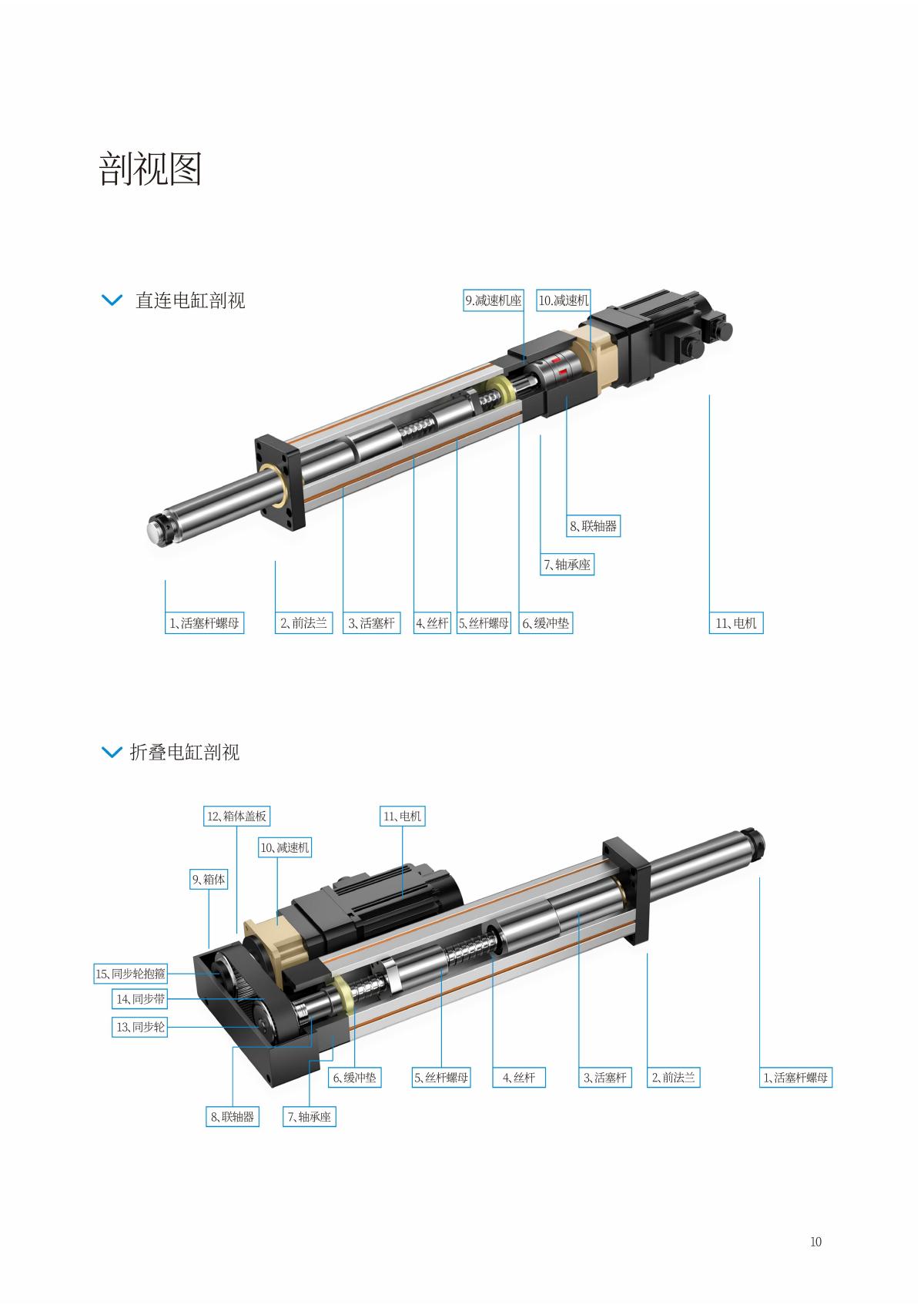
Motor torque, transmission ratio, screw lead and efficiency jointly determine thrust and speed. Choose in-line or parallel layouts to suit length, width and maintenance access, rather than body size alone. Handbook diagrams explain transmission arrangements; they do not establish inclusion of sensors, controllers or safeguarding in a complete press system.
 View full image ⤢
The handbook compares motor, transmission and screw arrangements. Evaluate overall length, width and maintenance access, then select torque, ratio, lead and duty cycle together. This supplier reference does not define dimensions or rated loads for a specific product on this site.
Third-party reference · Image source:Electric-cylinder handbook · PDF p.2 / printed p.10Six inputs for engineering
① Continuous and peak loads plus dwell; ② working stroke and approach/press/return speeds; ③ cycle time, daily operating hours and acceleration; ④ horizontal or vertical mounting, braking and anti-drop needs; ⑤ side loads, eccentric loads, guidance and attachments; ⑥ position/force feedback, control interfaces and data retention.
Define your configuration
Motion & duty cycle
Continuous/peak loads, speed, acceleration, cycle time and daily hours; confirm braking and anti-drop for vertical axes.
Space & loads
Force, working stroke, daylight, table and eccentric loads; check tooling and loading clearance together.
Supply & integration
Scope for actuator, motor/drive, sensors, controller, cables, tooling and guarding; define PLC/MES interfaces.
Module integration & acceptance scope
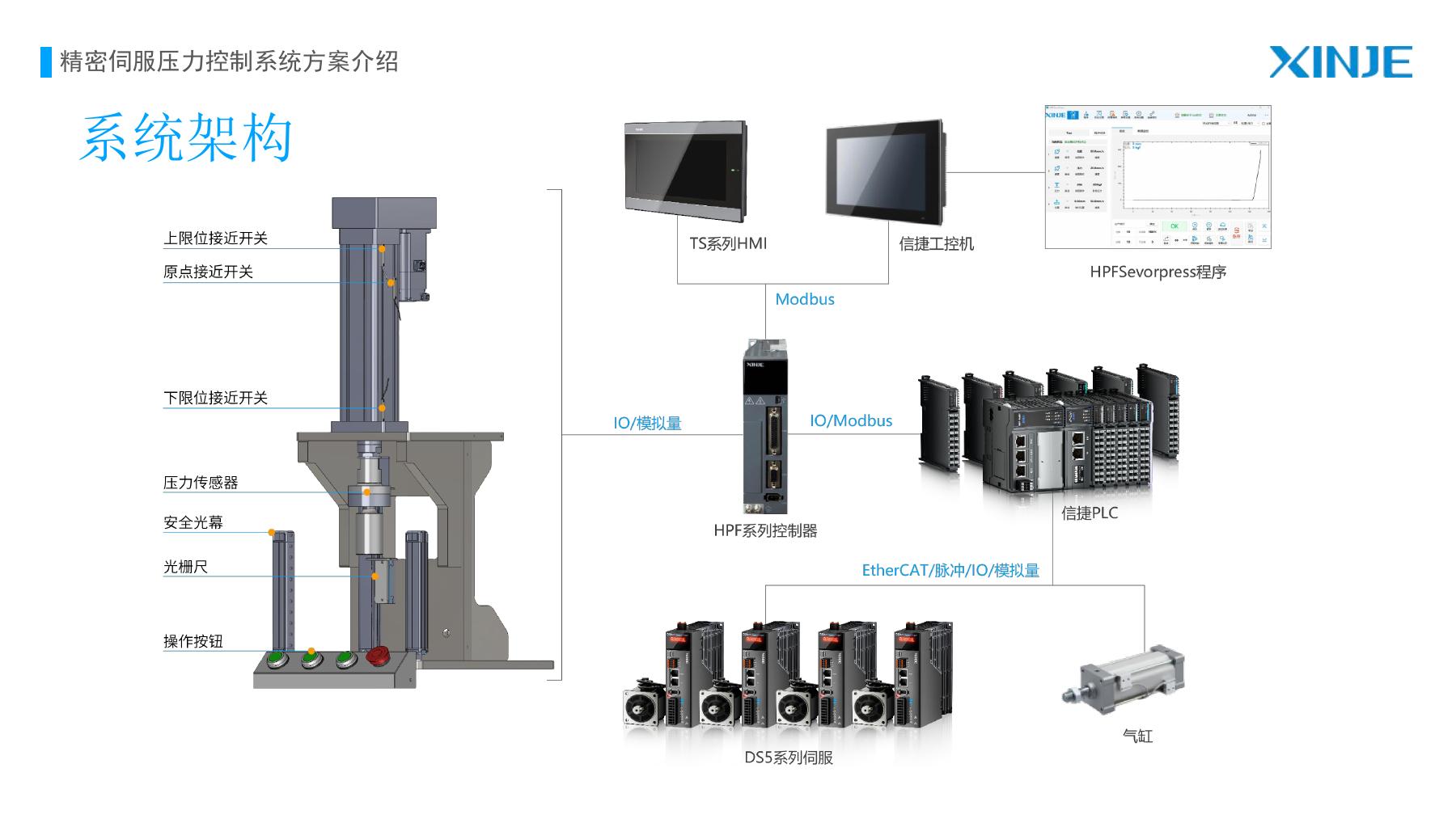
Identify supply scope for actuator, motor/drive, force sensor, controller, cables, tooling and guarding. Validate calibration, zeroing, mechanical limits, interlocks, fault recovery and host-system handshakes on the complete machine. A floating head is a tooling option to evaluate; it does not replace sound location or correct arbitrary errors.
 View full image ⤢
The XINJE HPF diagram explains system components and connections. It is a third-party option for evaluation, not a Zhongcheng-developed system or standard hardware for every machine. Confirm components, protocols and versions per project.
Third-party reference · Image source:XINJE Electric · HPF solution · p.4